The Viewing Tool
The Viewing Tool has four sections shown as index cards,
Camera, Effects,
Rotation and
Side View.
Only one card is shown at a time, and clicking the tab for another
brings it to the front.
Close dismisses the Viewing Tool; Help opens
this manual page in a browser window.
The Camera section of the Viewing Tool
describes and allows adjustment of the view shown in the graphics window.
There are several ways to start
Camera, a tool in the Viewing Parameters category.
Default settings are indicated in bold.
- camera mode (cross-eye stereo/mono/stereo/stereo left
eye/stereo right eye/VRex row stereo/wall-eye stereo) - the stereo
mode will only work when --stereo
has been specified at the time of Chimera startup.
- projection (perspective/orthographic) -
perspective causes
atoms and bonds further from the viewer to appear smaller, and is
indicated in the Side View by red lines
diverging from the eye position. An orthographic
projection has no scaling-with-distance effect, and is indicated
in the Side View by horizontal red lines.
- scale factor (1 when a structure is first opened) -
a factor reflecting the cumulative effects of scaling with
the mouse, the Side View, and/or the command
scale
- near plane - Z-coordinate of the front (hither) clipping plane
- far plane - Z-coordinate of the back (yon) clipping plane
The Effects section of the
Viewing Tool
describes and allows adjustment of visual effects.
There are several ways to start
Effects, a tool in the Viewing Parameters category.
Default settings are indicated in bold.
- depth cueing (on by default)
causes regions farther from the viewer to be shaded (less intense)
- start ratio (0.2) - how far behind the front
clipping plane any decrease in intensity begins, expressed as a fraction
of the total distance between the clipping planes
- yon intensity (0.1) - the intensity of the nominal colors
at the back (yon) clipping plane. The intensity decreases linearly from 1.0
at the plane defined by the start ratio to a value of
yon intensity at the back clipping plane.
- color (a color well,
black by default) -
the color used for shading (depth cueing).
As the intensity of the nominal colors decreases,
the intensity of the shading color increases.
When set to No Color, the shading color will be the same as the
background color (which can be controlled in the
Background preferences).
- subdivision quality (1.0) -
the stick, ball-and-stick, and sphere
representations consist of curved surfaces approximated by collections
of planes; increasing the subdivision quality increases the number of planes
and the apparent smoothness.
This setting does not affect
molecular surfaces or ribbons.
The Rotation section of the
Viewing Tool describes and allows adjustment of rotation parameters.
There are several ways to start
Rotation, a tool in the Viewing Parameters category.
Default settings are indicated in bold.
- center of rotation method:
- fixed - uses the rotation center coordinates
- center of models - sets the center of rotation to
the center of the bounding box of all
active models (displayed
portions only; may include items that are
invisible)
- independent - makes each model rotate around its own center
rather than one determined collectively; equivalent to the command
set independent
- center of view - continually adjusts the center of
rotation to the current center of view
- rotation center (X, Y, and Z coordinates)
- editable only when the center of rotation method is fixed,
meaningless when models are set to rotate independently
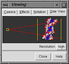
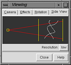
The Side View section of the
Viewing Tool provides a convenient and intuitive way
to scale and to move the clipping planes.
There are several ways to start
the Side View, a tool in the Viewing Parameters category.
The small square on the left represents the user's eye position, and the
two vertical lines represent the hither and yon clipping planes.
Each of these may be moved by dragging with the left mouse button.
Movement of the eye position closer to or farther from the items being
viewed scales them up or down.
A miniature version of the display shows the relationship between
the eye position, the displayed item(s), and the clipping planes.
By default, the miniature
is shown at full resolution, with colors and representation types the same
as the main display. Setting Resolution to low
simplifies the miniature to only the backbone of any peptide and nucleic
acid residues shown in the main display. In the
low-resolution version, surfaces and objects are indicated by
bounding box outlines. Using low resolution is recommended if performance
seems slow when large molecules are being viewed.
Dragging the hither clipping plane (the one closer to the eye position)
with the middle mouse button moves both clipping planes in
the same direction (like using the command
section).
Dragging the yon clipping plane with the middle mouse button
moves the clipping planes in opposite directions (like using the command
thickness).
Note that holding the Shift key down will reduce the speed
(mouse sensitivity) of manipulations in the main window and
Side View by a factor of 10.
The red lines show the field of vision.
The use of perspective may be turned off by specifying
the orthographic projection (see the
Camera section).
The Side View will then show parallel rather
than diverging red lines.
The clipping planes shown in the Side View act globally (on all models).
Models can be clipped individually and at any angle using the
Per-Model
Clipping tool.