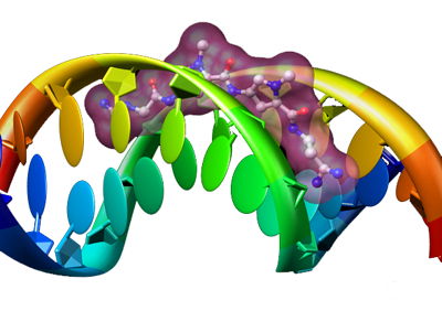
Netropsin bound to double-stranded DNA (PDB entry 6bna).
Taken from the
Chimera Image Gallery.
In addition to its utility as an in-depth analysis tool, Chimera also
has many helpful facilities for creating presentation-quality media
in the form of still images or movies.
This tutorial will cover the usage of several of these tools.
It is organized as follows:
Netropsin bound to double-stranded DNA (PDB entry 6bna).
Taken from the
Chimera Image Gallery.
The system that will be used throughout this tutorial is is
the PDB model 1BNA (structure of B-DNA dodecamer).
Open the file 1BNA.pdb by choosing File→Open
from the Chimera menu and browsing to the file.
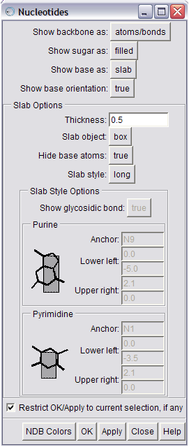
The Nucleotides tool can be used
to create
abstract representations of nucleic acid
models.
Chimera's Nucleotides tool can be used to obtain highly stylized renditions of nucleotide structures, including VRML (Virtual Reality Modeling Language) representations of the base and sugar moieties.
Start Chimera's Nucleotides tool ( Tools→Depiction→Nucleotides).
You can click the NDB Colors button at the bottom of the panel to use the standard Nucleic Acid Database coloring scheme. Try changing other parameters on the Nucleotides dialog to alter the characteristics of the abstract rendering. For example, one configuration could be:
| Show backbone as: | ribbon |
| Show sugar as: | tube |
| Show base as: | slab |
| Show base orientation: | false |
| Thickness: | 0.5 |
| Slab object: | ellipsoid |
| Hide base atoms: | true |
| Slab style: | big |
When you have set the desired parameters, press the Apply button to see the changes applied to the model in the graphics window. When you are satisfied with the nucleotide representation, dismiss the Nucleotides dialog by clicking on the Close button.
The little dots that look like a starfield surrounding the model
are water molecules.
They can be undisplayed in one of several ways.
You can select one water molecule by
Ctrl-left-clicking on it,
then press the ↑ (up-arrow) key
to promote the selection to include all the molecules in the water chain.
Alternatively, you can select the water chain by choosing
Select→Chain →water from the Chimera menu.
Then undisplay the selection by using the command ~disp sel
in the Command Line.
One more refinement to try is changing the representation style
of the ribbon by either issuing the command ribrepr smooth,
or choosing Actions→Ribbon→round
from the menu. Other available ribbon representations are
flat and edged.
The next set of tools enables you to manipulate visual settings in Chimera.
They are accessible as tabs on the Viewing tool,
or directly from the Viewing Controls menu
(Tools→Viewing Controls).
Lighting | ||||||||
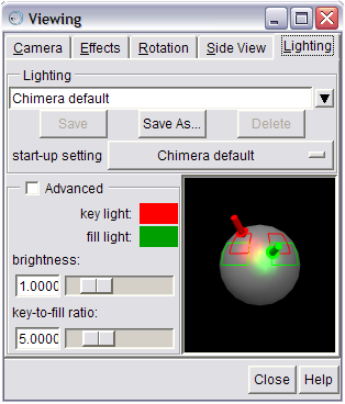
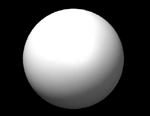
The Lighting tool lets you change the position of Chimera's two lights. |
The scene starts out a little too dark for viewing this model. Chimera uses two separate sources of light to light the scene. The orientation these two lights can be changed using the Lighting tool (Tools→Viewing Controls→Lighting). This tool lets you create custom lighting configurations, then save them into your preferences for future use. The key light provides the main illumination of your models while the fill light is intended to fill in dark areas. The red and green outlines on the sphere (for the key light, and fill light, respectively) represent directions that typically give favorable results. Try dragging the lights around and seeing how it affects the scene in the graphics window. See the discussion of lighting for more on information on lighting in Chimera. |
|||||||
|
||||||||
 |
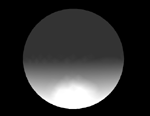
&rarr |  |
|
 |
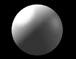
&rarr |  |
|
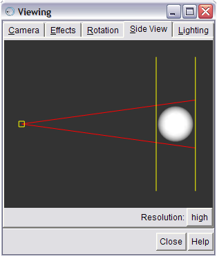
An object that is far from the front clip plane (top), will appear dark, while an object that is close to the front clip plane (bottom) appears brighter. |
|||
Chimera dims parts of the scene that are further from you to give a sense of depth (called depth cueing). This feature can be turned off by unchecking the depth cueing checkbox in the Effects dialog (Tools→Viewing Controls→Effects). This dialog also lets you change other characteristics of depth cueing, such as color; different color backgrounds may look better with a corresponding depth cueing color.
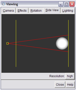
The dimming of the scene occurs between the near and far clip planes. The clip planes can be adjusted in the Side View tab of the Viewing tool (also accessible directly from the menu — Tools→Viewing Controls→Side View). The Side View window displays the open models as seen from the side. Two vertical yellow lines indicate the front and back clip planes. The left line is the front clip plane. If you drag the front clip plane (yellow vertical line) towards the models with the mouse you will see the brightness in the main graphics window increase (provided depth cueing is turned on). If you move the front clip plane so it intersects the models, you will see the surface cut in the main graphics window.
The small yellow box at the left in the Side View is your eye position. You can drag this right or left to zoom in and out.
The Effects dialog also allows you to control rendering quality. The smoothness of curved surfaces in the stick, ball-and-stick, sphere, and ribbon molecular representations can be increased by raising the subdivision quality. Higher values increase smoothness but may slow performance. When saving images, the quaility is temporarily increased to 5 if it is lower. The maximum quality is 20.0. The default quality of 1 is designed for interactive use.
Similarly, the smoothness of molecular surfaces (not included in this example) can be increased by increasing the vertex density in the surface attributes panel (opened by choosing a surface model in the left side of the Model Panel [Tools→General Controls→Model Panel] and then clicking attributes... on the right).
You can control how shiny the models appear using menu entry
Tools→Viewing Controls→Shininess Control.
The shininess parameter effects the size of specular highlights.
Specular highlights are the lighting spots on the model.
The brightness parameter just effects
the brightness of the highlights, not the whole surface.
The background can be any color, but white is often good for publication.
The background color can be changed by issuing the
set bg_color command
(e.g., set bg_color white),
using Actions→Color in the menu,
or setting Background color in the
Background preference category
(Favorites→Preferences).
Further, if system hardware permits, starting Chimera with the
--bgopacity option enables background transparency.
Images saved with a transparent background are easier to composite
with different backgrounds in image-editing applications.
Two tools control all the options for saving images in Chimera — the Save Image panel and the Image Setup preferences category.
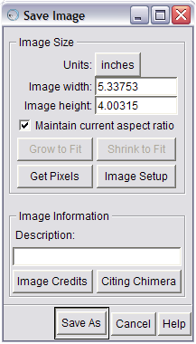
The Save Image dialog can be used
to specify the target size of the
image to be saved.
Use the menu entry File→Save Image to open the Save Image panel. This panel lets you specify the target dimensions for your image. The dimensions can be specified directly in pixels, or in units of length. If units of length, the number of pixels per unit can be controlled in the Image Setup preferences category.
If you want an image with exactly the same number of pixels as the Chimera window on the screen, press the Get Pixels button. This fills in Image width and Image height with the exact size in pixels of the Chimera graphics window.
It is important that the aspect ratio of the graphics window
match the aspect ratio of the desired image size.
When the Maintain current aspect ratio checkbutton
is on,
editing the value for one dimension (Image width or
Image height)
and then clicking in the field for the other
dimension adjusts the latter automatically.
When the Maintain current aspect ratio checkbutton
is off, you must either use
Grow to Fit (make one dimension larger)
or Shrink to Fit (make one dimension smaller)
to make the aspect ratio of the graphics window
match the aspect ratio dictated by Image width and
Image height.
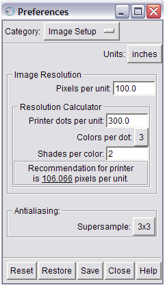
The Image Setup preference category
The Image Setup preferences category sets specifications for images saved to files using the Save Image panel.
For example, if a journal requirement calls for an image to be
85 mm (3.346 in) with a resolution of at least 300 dpi,
you could use the Save Image panel
to set Units to inches and
Image width to at least 3.346, then use
the Image Setup preferences to set
Pixels per unit to 300.
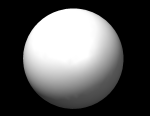 |
|
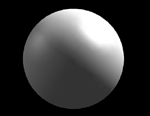
The image without supersampling (left) has jagged edges around the perimeter of the sphere, while the supersampled image (right, supersampling set to 6x6) has smoother edges. | |
The Image Setup preferences can also be used
to set the level of supersampling.
Sometimes straight edges in the graphics window may appear
as tiny zigzags, especially against a white background.
Supersampling gets rid of such jagged edges within saved images
by making an initial image larger than that requested
and then sampling it down to the final size.
The default value of 3x3 is generally
sufficient for publication.
To generate stereo images, change the camera mode
setting in the Camera tool
(Tools→Viewing Controls→Camera)
before saving an image file.
Due to current problems with the cross-eye stereo
and wall-eye stereo options,
the best approach is to save separate images using the
stereo left eye
and stereo right eye options
and assemble them in the desired order to give a cross-eye or
wall-eye stereo image.
Once all the desired options have been set, press the Save As button on the Save Image panel to save to a file.
Clicking Save As causes the image to be redrawn in an appropriate size for saving. Because this is generally a different resolution than that shown on the screen, different portions of the image will "flash" within the graphics window.
Note: It is important that you don't move any windows on top of the Chimera graphics window while saving an image and that the Chimera graphics window be completely on-screen. Because of current limitations in the way Chimera saves images, any window that is placed over the graphics window (or clipping due to being partially off-screen) while Chimera is capturing its contents will make an unwanted appearance in the saved image.
When the image computation is finished,
a file name and file type (format) can be specified, or the save
can be canceled.
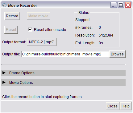
The Movie Recorder tool lets you make a movie
from the contents of the graphics window.
Chimera's Movie Recorder tool enables you to make movies from the contents of the graphics window. The movie recording process can be split into two steps:
Open the Movie Recorder dialog by selecting
Tools→Utilities→Movie Recorder
from the Chimera menu.
Buttons that control frame recording and movie encoding
are at the top of the dialog.
The Status section keeps track of information
such as the number of frames that have been captured
and the current size of the Chimera graphics window.
Advanced options can be found in the Frame options
and Movie options sections,
which are hidden by default.
These sections can be expanded by clicking on the right arrow
next to their respective label
(these options are described at the end of this section).
Moving images are composed of a series of single frames, shown in rapid succession. Film in a movie theatre is played back at 24 frames per second, video on Digital Video Disc (DVD) is shown at 30 frames per second, etc. Thus, the first step to making a movie is capturing a series of frames.
Download dna-movie.cmd
(a Chimera command file) to an easily accessible location on
your computer.
It contains a series of commands that will change the orientation
of the open 1BNA model over the course of many frames.
Choose File→Open from the menu to bring up the
Open File dialog.
Browse to the location where you saved dna-movie.cmd
but don't open it just yet — you'll want to start
recording before executing this file.
Keep the Open File dialog open;
you'll be needing it again shortly.
The Status section displays the current size of the Chimera graphics window. When the size of the graphics window changes (e.g., you resize the window), this will automatically be reflected in the Status section of the Movie Recorder dialog.
The resolution of the graphics window directly affects the
resolution of the frames that are captured,
and the subsequent resolution of the movie that is encoded:
if the graphics window is 512 pixels wide by 384 pixels high (512x384),
all captured frames will be 512x384, and by default,
the resulting movie will have a resolution of 512x384.
It is not advisable to change the size of the Chimera window
when you already have some frames recorded, as encoding a movie
from different-sized frames will most likely cause the encoder to crash.
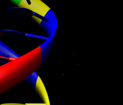
This is what the graphics window will
look
like when the dna-movie.cmd script has
finished running. Press the Stop button!
This next part calls for some planning.
The goal is to start recording frames,
then quickly open the command file (dna-movie.cmd)
that was downloaded earlier.
One way to do this is to have both
the Movie Recorder dialog
and the Open File dialog open,
with the Open File dialog
already browsed to the file.
Take a deep breath, click Record
(on the Movie Recorder dialog),
then click Open
(on the Open File dialog),
then sit back and watch... the script runs for about three
minutes and should consume about 2500 frames,
depending on the speed of your machine.
The Status section keeps track of the number
of frames that have been recorded.
You may notice that Chimera appears to slow down
while frames are being captured; this is normal,
and happens because Chimera is working hard trying to save a picture
of the graphics window many times per second.
When Chimera has finished running the script, all motion will stop,
and the DNA model will be positioned vertically,
half-off the left-hand side of the window.
Click the Stop button
(which was formerly labeled Record)
to stop capturing frames.
Now it's time to add some annotations to the scene.
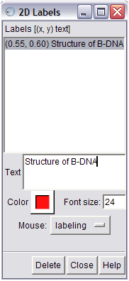
The 2D Labels tool lets you place
two-dimensional
labels in the
graphics window.
Chimera's 2D Labels tool can be used to place labels of arbitrary text, font size, and color within the Chimera graphics window. These labels are saved in Chimera session files, and they can be saved in images.
Note:The frames that are saved by
Movie Recorder are not supersampled.
Start the 2D Label tool by selecting
Tools→Utilities→2D Labels from the
Chimera menu.
To make a new label, click into the Chimera graphics window
and just start typing.
You will see your text appear as a label in the graphics window,
as well as in the box labeled Text
in the 2D Labels dialog.
Click and drag on a label in the Chimera graphics window
to move it to a new location.
You can change the size of the label
by entering a new Font size
and pressing Return,
or the color by clicking on the color well (box with a raised border)
labeled Color and selecting a new color.
To delete a label, select it from the Labels list
and click the Delete button at the bottom of the dialog.
When the 2D Labels dialog is displayed,
left-mouse clicks in the Chimera graphics window
(which are normally interpreted as model rotation)
are assumed to be label-related,
i.e., intended to create a new label or move an existing one.
The Mouse drop-down menu
in the 2D Labels dialog reflects this state;
it is by default set to labeling.
So if you are trying to rotate a model in the graphics window
and it does not appear to be responding,
it could be that you forgot to Close
the 2D Labels dialog,
and you just unknowingly added a new label.
You can restore the normal mouse behavior (e.g., model rotation)
while the 2D Labels dialog is displayed
by selecting the normal setting
from the Mouse drop-down menu.
Additionally, Closeing
the 2D Labels dialog
will return left-mouse click behavior to normal.
| → | ||
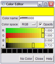 |
→ | 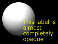 |
A lower opacity value on the 'A' slider (top)
makes a color more transparent
(less opaque), while
a higher opacity (bottom) makes it
less transparent (more opaque).
One neat trick is to use the opacity of label colors to give the effect of fading in or out over a series of frames. Add a label to the Chimera graphics window as described above. In the 2D Labels dialog, select a label, then click on the color well. Click the checkbox called Opacity. This adds another slider, labeled A to the existing R, G, and B slider bars. Moving the A slider bar to the left (lower values) results in a color with lower opacity, or more transparency, while moving it to the right (higher values) achieves the opposite affect. Thus, labels can be essentially hidden by setting their opacity to zero. Try starting with zero opacity, and slowly moving the slider to the right for a fade-in effect.
Restart the capturing of frames,
which will now include the annotations added with
2D Label,
by clicking the Record button in the
Movie Recorder dialog.
This will append frames to the existing series already captured.
Click Stop when you are finished adding labels.
Now that you have some frames saved up (as evidenced by the # Frames field in the Status box), you can make a movie. You can specify where you would like the movie to be saved by typing in or browsing for a filename in the Output file field. The default movie format is MPEG-2 (.mp2), but you can select a different format from the Output format drop-down box. Now click the Make movie button to encode a movie file from saved frames. Status information will appear at the bottom of the Movie Recorder window.
Once the movie has finished encoding, the Status will change to reflect the result of the encoding process (Successfully encoded if everything went smoothly, Encoding error if an error occured during encoding, or Canceled if encoding was canceled by clicking on the Cancel movie button). The path describing where the movie was saved (or any errors, if something went wrong) will be printed to the Reply Log.
Note that while it is possible to encode a movie at a different
resolution than the size of the frames that comprise it
(by choosing a preset video format,
as described below in the
Advanced movie encoding options section),
encoding a movie at the same resolution
as its source frames will result in better quality.
If the movie is encoded successfully, the default behavior is for the Movie Recorder to reset, setting the frame count back to zero and enabling you to start another movie. This "automatic reset" behavior can be controlled by toggling the Reset after encode checkbutton at the top of the Movie Recorder dialog.
By default, when the Movie Recorder is reset
(either as a result of a movie being successfully encoded,
or as a result of manually pressing
the Reset button),
all frames that have been saved during the recording phase are deleted.
However, it may be desirable to keep these frames,
e.g. to use in another video editing application.
Enabling the Save images on Reset checkbutton,
located in the Frame Options section,
will ensure that captured frames are saved.
The location and names of the saved frames are dictated
by the Directory
and Filename pattern options.
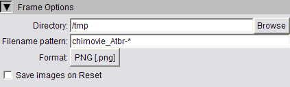
The Frame Options section
 |
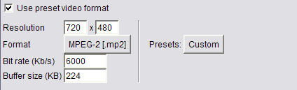 |
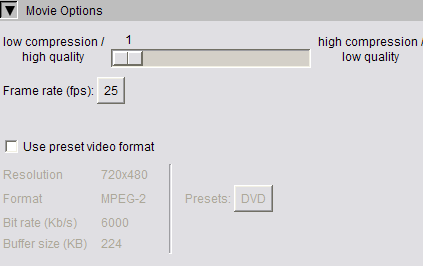
The Movie Options section (top) lets you specify advanced options related to movie encoding. You can choose the 'Custom' preset (bottom) to override the values of a preset format. |
The settings in the Frame Options section
control several aspects of how frames are saved.
You can specify the directory into which frames will be stored
(Directory),
the pattern by which sequential frames will be named
(Filename pattern),
the image format of saved frames (Format),
and whether the captured frames should be saved when the
Recorder is reset (Save images on Reset).
The settings in the Movie Options section
control several parameters of the movie encoding process.
The slider bar lets you specify the tradeoff between movie quality
and compression,
and the Frame rate option
lets you choose the target frame rate of the movie in frames per second.
Clicking on the Use preset video format
option enables you to choose one of several standardized video formats,
each with associated encoding parameters
such as Format
and Resolution.
Choosing the Custom preset
lets you customize the parameters for a given video preset.
Note that if Use preset video format is selected,
it overrides the format specified
by the Output format option
at the top of the Movie Recorder dialog.
The functionality of Movie Recorder
is accessible from the command line with the
movie command.
While using the Movie Recorder graphical interface
may be easier for interactive use,
the movie command can be very useful in a scripting context.
For example, if you have a script that opens a model,
changes the representation,
then executes some commands to change the orientation,
you can add a few movie commands
to automatically start capturing frames once the model is set up,
then encode a movie once all orientation changes have occurred.
For example:
open 1gcn
color cornflower blue
surf
# start capturing frames, in .png format
movie record fformat png
roll y 1 180; wait
roll z 1 90; wait
roll y 1 180; wait
close #0
# stop recording frames
movie stop
# write status information to reply log
movie status
# encode a movie in mp4 format from recorded frames
movie encode mformat mp4 output C:\\tmp\\path-to-movie.mp4
The documentation page for the
movie
command has more information about its usage.
Here are links to more information about the topics covered in this tutorial: