

|
|
This tutorial describes how to reveal an interface by splaying it open like a book. The structures are shown as surfaces with interactive shadows. See also: Intersurf, presets, tips on preparing images
Start Chimera and show the Command Line (for example, with Favorites... Command Line). Fetch Protein Data Bank entry 1avx:
Command: open 1avxThe structure contains porcine pancreatic trypsin, chain A, complexed with a trypsin inhibitor from soybean, chain B. Move and scale (zoom) with the mouse to see how the two proteins fit together. Resize the window as desired, either by dragging its lower right corner with the mouse or by using the command windowsize. The window dimensions define the aspect ratio (width:height) of output images, but image resolution can be specified independently when an image is saved. An 800x500-pixel window was used for the example images at right.
In chain B, there is a break in the ribbon and a dashed line where atomic coordinates could not be resolved. Hide this dashed line “pseudobond”:
Command: ~longbond
Use the all-atoms preset and delete solvent:
Command: preset apply int 2
Command: del solvent
Split the model and assign the resulting models different colors:
Command: splitSplitting the model facilitates moving the chains independently, and is also one way to make molecular surfaces enclose each chain separately instead of both chains collectively. The original model #0 is now model #0.1 (green) containing chain A, and model #0.2 (purple) containing chain B. Models are listed in the Model Panel (under Favorites in the menu).
Command: color sea green #0.1
Command: color medium purple #0.2
Color the interface regions differently so that it will be clear, when the proteins are separated, which sides should be rotated to face the viewer. To avoid typing long commands, you can copy text from this page and paste it into the Command Line:
Command: findclash #0.1 test #0.2 intersub true overlap -1 hb 0 make false select true
Command: namesel contacts
Command: ~select
Command: color yellow contacts & #0.1
Command: color hot pink contacts & #0.2
Show the molecular surfaces:
Command: surfaceIf you wish to save your work at any point, save a session file (see the File menu).
The plan is to:
Create aliases to separate and rotate the proteins, since you may want to repeat the process starting from different initial orientations:
Command: alias ^separate move x $1 model #0.2; focus
Command: alias ^face-me set independent; turn y -90 model #0.1; turn y 90 model #0.2; ~set independent
These aliases assume that you have aligned the complex so that #0.1 (trypsin, green) is on the left and #0.2 (inhibitor, purple) is on the right. Aliases can be used in the Command Line, and face-me also appears in the Aliases menu; separate does not, because it requires also entering the distance of separation (Å). The “^” symbol means the alias should only be expanded when it appears at the beginning of a command. In the independent rotation mode, each model rotates about its own center rather than a single collective center.
Next, generate initial trial positions by moving the complex with the mouse. Again, a good initial position of the complex has trypsin on the left and the inhibitor on the right, with the interface approximately edge-on (similar to the top image above). If you have already separated the proteins and/or rotated them independently, first put the complex back together:
Command: resetStart the Side View (under Favorites in the menu) and place it beside the Chimera window so that you can see the structure from two directions at once. By default, Chimera uses perspective, in which nearer parts of structures appear larger. This enhances 3D perception, but subtly distorts structures as the eye proceeds from the center of the Chimera window towards the edges. The orthographic projection (no perspective) is better for certain images such as side-by-side comparisons:
Command: set projection ortho
When you have what seems to be a good initial position, save it before applying any aliases, for example:
Command: savepos p1
The position can be restored later as needed, with:
Command: reset p1
You can save/restore multiple positions using different names (p1 above). Positions are included in subsequently saved session files. After generating one or more candidate initial positions, try rotating and separating the structures, for example:
Command: separate 20
Command: face-me
Command: separate -5
Starting from the intact complex, separate can be used multiple times, but face-me should only be used once, and any other rotation, manual or otherwise, should be avoided. However, it is fine to scale or translate the view as a whole using the mouse (carefully!) and/or commands, for example:
Command: scale 1.4
Command: move y -2
After achieving a good final view for the figure, you may want to save another position. It can be fun and even instructive to reset to a saved position gradually, over a specified number of image update frames:
Command: savepos p2
Command: reset p1 60
Command: reset p2 60
Many different visual effects can be applied, and choosing which to apply depends on both personal taste and what the image is meant to illustrate. The example images above were made with smooth molecular surfaces, a white background, and shadows:
Command: setattr s density 8
Command: back solid white
Command: set shadows
The vertex density of a molecular surface controls the fineness of triangulation, with higher values (default 2) giving a greater number of smaller triangles and thus a smoother surface.
 |
 |
Of course, many other combinations of effects and coloring schemes are possible. Just to name a few, surfaces could be colored to show hydrophobic/hydrophilic compatibility or electrostatic complementarity as in the Surface Properties tutorial, conservation within associated sequence alignments as in the Sequences and Structures tutorial, or concavity/convexity as in the Attributes tutorial, part 2. A color key and text could be added, as in the B-factor Coloring tutorial.
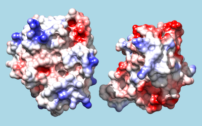
If a coloring scheme includes white, it may be helpful to make the background a different color:
Command: back solid light blue
To color by Coulombic electrostatic potential:
Command: coulombic -10 red 0 white 10 blue
The result shows a predominantly positive protuberance on the inhibitor (right) interacting with a primarily negative pocket on the enzyme (left), with the opposite charge pattern on surrounding areas.
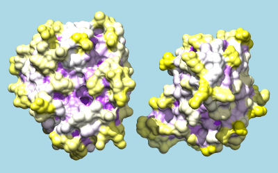
To color by per-residue concavity/convexity, open the Attribute Calculator (Tools... Structure Analysis... Attribute Calculator). Calculate a new attribute named convexity for residues using the Formula
residue.areaSAS/residue.areaSESValues of convexity > 1 represent convex areas, while values < 1 represent concave areas. Click OK to perform the calculation and assignment. A warning message will appear because some residues have an areaSES of zero, resulting in a divide-by-zero error. However, just close the warning dialog; values have been assigned correctly to the remaining residues. The coloring command could be something like:
Command: rangecolor convexity min purple 1 white max yellow
The result mainly serves to emphasize what is already evident from the shadowed surfaces: that a knobby protuberance on the inhibitor plugs into a socket on trypsin. The Attributes tutorial, part 2 describes showing per-atom rather than per-residue convexity, but the results are similar.