The Viewing Tool
The Viewing Tool has five sections shown as index cards,
Camera, Effects,
Rotation,
Side View, and
Lighting.
Only one card is shown at a time, and clicking the tab for another
brings it to the front.
Close dismisses the Viewing Tool; Help opens
this manual page in a browser window.
The Camera section of the Viewing Tool
describes and allows adjustment of the view shown in the graphics window.
There are several ways to start
Camera, a tool in the Viewing Controls category.
Default settings are indicated in bold.
- camera mode
(cross-eye stereo/mono/red-cyan stereo/stereo/stereo
left eye/stereo right eye/VRex row stereo/wall-eye stereo) -
camera mode refers to any of several
stereo and mono viewing options. The stereo mode
(sequential stereo) may not be
available, depending on the system.
- projection (perspective/orthographic) -
perspective causes
atoms and bonds further from the viewer to appear smaller, and is
indicated in the Side View by red lines
diverging from the eye position. An orthographic
projection has no scaling-with-distance effect, and is indicated
in the Side View by horizontal red lines.
- scale factor (1 when a structure is first opened) -
a factor reflecting the cumulative effects of scaling with
the mouse, the Side View, and/or the command
scale
- near plane - Z-coordinate of the front (hither) clipping plane
- far plane - Z-coordinate of the back (yon) clipping plane
The Effects section of the
Viewing Tool
describes and allows adjustment of visual effects.
There are several ways to start
Effects, a tool in the Viewing Controls category.
Default settings are indicated in bold.
- depth cueing (on by default)
causes regions farther from the viewer to be shaded with the
depth-cueing color
- start ratio (0.5) - how far behind the front
clipping plane any decrease in intensity begins, expressed as a fraction
of the total distance between the clipping planes
- yon intensity (0.1) - the intensity of the nominal colors
at the back (yon) clipping plane. The intensity decreases linearly from 1.0
at the plane defined by the start ratio to a value of
yon intensity at the back clipping plane.
- color
(a color well, black by default)
- the color used for front-to-back shading (depth cueing).
As the intensities of the nominal colors decrease, the intensity of the
shading color increases. When set to No Color, the shading color
will be the same as the
background color.
- subdivision quality (1.0, maximum 20.0) -
the stick, ball-and-stick, sphere, and ribbon
representations
consist of curved surfaces approximated by collections of planes;
increasing the subdivision quality increases the number of planes
and the apparent smoothness.
If subdivision quality is set to a value below 5.0, it will be
raised to 5.0 temporarily when an image is saved.
This setting does not affect
molecular surfaces.
- local viewer (true/false) - whether for lighting purposes
the actual (local) position of the viewer is used. The alternative of
treating the viewer as infinitely far away simplifies the lighting
calculations and is more computationally expedient. The difference
in appearance is generally quite subtle.
- transparent background (true/false)
- whether to make the background transparent and allow its opacity to be
adjusted (opacity = 1 – transparency). Not all systems have the
hardware required to support this option.
PNG and TIFF images saved
from the session will include opacity information,
making them easier to composite with different backgrounds
in image-editing applications. (Note: TIFF images with
background transparency may not be interpreted correctly by Adobe
Photoshop®.)
With this option, the opacity is initially set to zero;
if the background color is subsequently changed, however,
the background will no longer be transparent unless the color
definition includes transparency.
Background transparency can also be enabled with the
startup option --bgopacity.
- silhouette edges (off by default)
highlights borders and discontinuities with a thin outline in the
silhouette color
- color
(a color well,
No Color by default)
- when set to No Color, the silhouette color will be gray if
the background is black, otherwise black.
The Rotation section of the
Viewing Tool describes and allows adjustment of rotation parameters.
There are several ways to start
Rotation, a tool in the Movement category.
Default settings are indicated in bold.
- center of rotation method:
- fixed - uses the rotation center coordinates
- center of models - sets the center of rotation to
the center of the bounding box of all
active models (displayed
portions only; may include items that are
invisible)
- independent - makes each model rotate around its own center
rather than one determined collectively; equivalent to the command
set independent
- center of view - continually adjusts the center of
rotation to the current center of view
- rotation center (X, Y, and Z coordinates)
- editable only when the center of rotation method is fixed,
meaningless when models are set to rotate independently
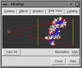
The Side View section of the
Viewing Tool provides a convenient and intuitive way
to scale and to move the clipping planes.
There are several ways to start
the Side View, a tool in the Viewing Controls category.
The small square on the left represents the viewer's eye position; the
two vertical lines represent front and back (hither and yon) clipping planes.
Each of these may be moved by dragging with the left mouse button.
Dragging the eye position closer to or farther from items in the view scales
them up or down, like using the command
scale.
Dragging either clipping plane is like using the command
clip.
Dragging the hither clipping plane with the middle mouse button
moves both clipping planes in the same direction (like the command
section).
Dragging the yon clipping plane with the middle mouse button
moves the clipping planes in opposite directions (like the command
thickness).
Simultaneously holding down the Shift key reduces the speed
(mouse sensitivity) of such operations by a factor of 10.
Clicking View All adjusts the scale and clipping plane
positions so that the view will include everything that is displayed
(possibly including items that are
invisible
). Model rotations and translations are not adjusted.
A miniature version of the display shows the relationship between
the eye position, the displayed item(s), and the clipping planes.
By default, the miniature display
is shown at high resolution, with colors and
representations the same
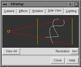
as in the main display. Setting the resolution to low
simplifies the miniature to only the backbone of any peptide and nucleic
acid residues shown in the main display. In the
low-resolution version, surfaces and objects are indicated by
bounding box outlines. Low resolution is recommended if performance
seems slow when large molecules are being viewed.
The red lines show the field of vision.
The use of perspective may be turned off by specifying
the orthographic projection (see the
Camera section).
The Side View will then show parallel rather
than diverging red lines.
The clipping planes shown in the Side View act globally.
Models can be clipped individually and at any angle using the
Per-Model
Clipping tool.
The Lighting section of the
Viewing Tool
allows lighting parameters to be changed and saved.
There are several ways to start
Lighting, a tool in the Viewing Controls category.
In brief, the key light is generally the dominant (brighter)
source of light; the fill light serves as a secondary source.
Each light includes diffuse and specular contributions.
Diffuse light is scattered from a surface equally in all directions,
whereas specular light is reflected in a preferred direction. See the
discussion of lighting for more details.
 The basic lighting interface
includes sliders for controlling
The basic lighting interface
includes sliders for controlling
- brightness (1.0 by default;
possible values range from 0.0 to 5.0)
- key-to-fill ratio (5.0 by default;
possible values range from 1.0 to 20.0)
and a window in which the lighting directions
can be manipulated interactively. Each light source
(unless turned off) is shown with a
solid arrow that can be moved with the mouse.
Outlines on the sphere represent directions
that typically give favorable results. See the
discussion of lighting for
more on lighting directions.
Only the advanced lighting interface
allows a light to be turned off
or placed behind the sphere.
The settings collectively define a scheme that can be
named, saved, and later retrieved from the pulldown list
indicated by the solid black triangle next to the Lighting field.
Choosing a scheme from the list automatically applies it to the
view in Chimera. When the name Chimera default is shown, it is only
possible to save to a different name, using Save As....
When another name is shown, it is possible to
- Save the current scheme to the name shown
- use Save As... to save the current scheme
with a new name
- Delete the scheme whose name is shown
Named schemes are saved in the Chimera
preferences
file, and are only updated with any changes
when Save, Save As..., or Delete is used.
The settings in effect when a session is
saved
(whether or not the scheme has a name) are included in the
session file.
The named scheme designated as the start-up setting
will be used for the next session that uses the same
preferences
file, unless overridden by a
session file.
Activating the checkbox marked Advanced
opens an interface with additional parameters. In this interface,
activating the key light or
fill light checkbox lists the corresponding parameters.
Default settings are indicated in bold.
- active (true/false) -
whether the light is "on."
When the key and fill lights are both inactive, the lighting reverts
to a single white light aimed along the line of sight.
- diffuse color (a color well,
white by default)
- diffuse scale (defaults are
approximately 0.861 for the key light and
0.2 for the fill light) - multiplicative scale factor for the diffuse
light. Possible values range from -5.0 to 5.0, where
negative values result in subtraction of the diffuse light
(see the combination rules).
- specular color (a color well,
white by default)
- specular scale (defaults are
approximately 0.861 for the key light and
0.2 for the fill light) - multiplicative scale factor for the specular
light. Possible values range from -5.0 to 5.0, where
negative values result in subtraction of the specular light
(see the combination rules).
- direction (X, Y, and Z coordinates; by default, approximately
-0.383,0.707,0.707 for the key light and 0.259,0.259,0.966
for the fill light) - the apparent source location on a unit sphere
with positive X, Y, and Z pointing right, up, and out from the screen.
Light direction can be manipulated interactively in the window
containing a sphere. In the advanced interface, only
the solid arrow representing the currently
checked light can be moved with the mouse,
but it can be moved behind the sphere (not possible with
the basic lighting interface).
UCSF Computer Graphics Laboratory / July 2006